
Atlas® Narrow-Body Implants to Retain, Stabilize, and Cushion a Mandibular Denture
According to Gordon Christensen, DDS, 90% of all denture wearers are dissatisfied with their mandibular dentures because they are ill-fitting, unstable, and prevent them from enjoying an acceptable quality of life.1 While implants with locator attachments and/or bar clips have been used to support dentures, many of the 39 million denture wearers, especially those with atrophic mandibles, have been neglected as candidates for implant-retained overdentures because their ridges are too thin, the vertical height of available bone has been severely compromised, and/or the existing denture-base height necessary to retrofit the denture is inadequate.
The Atlas® Narrow-Body Implants/Tuf-Link™ silicone reline protocol (Dentatus USA, New York, NY) can provide all mandibular denture wearers, in about an hour, more stability, more retention, and more comfort?and with great advantages to the dentist and patient.
The length of treatment time is significantly reduced because the surgical portion foregoes the traditional 2-stage surgery. The narrow-body implants are placed without reflecting a flap and are immediately loaded. Because there are little to no lab fees and the implants/components are less costly, the procedure is more affordable to a greater number of patients.
The Atlas implants come presterilized with threads that have been mechanically roughened.
SURGICAL TECHNIQUE
Surgical preparation is minimally invasive and simple to accomplish. The drilling of the osteotomy in the mandible, anterior to the mental foramina, is as easy as most endodontic treatment in single rooted teeth.
Periapical and/or occlusal radiographs can be taken to determine the amount of vertical and horizontal bone. This can be augmented with physical measurements, including calipers that are especially useful in some of the buccal concavities of the mandible. The Atlas implants are available in 2.2 mm and 2.4 mm diameters and three different threaded lengths?7 mm, 10 mm, and 14 mm (Figure 1). Either diameter provides sufficient strength; however, the wider 2.4 mm diameter should be used whenever possible because it has a larger surface area for better osseointegration. When sufficient bone is available, use the 10 mm or 14 mm threaded lengths.
The location for each osteotomy should be marked on the edentulous ridge with a sterile marking pen, or a surgical guide may be used to ensure proper positioning. The Dentatus protocol recommends using four Atlas implants, two on each side of the midline for support and balanced chewing function.
Local infiltration provides adequate anesthesia in most of these cases, but if bilateral mandibular blocks are necessary, use a short-lasting local anesthetic.
Once the patient is anesthetized, the dentist can use a periodontal probe or the Profile (Dentatus USA) twist drill with a rubber stopper to punch through the soft tissue to bone at the marked implant positions. The thickness of the soft tissue should be recorded and taken into account when drilling the flapless osteotomy.
The osteotomies are made with the Profile needlepoint drill (Figure 2) at 2,000-2,500 RPM using a copious biocompatible sterile water or saline solution to prevent overheating the surrounding bone. In mandibular D-1 and D-2 hard bone, the osteotomy should be drilled one millimeter past the full depth and then further enlarged with the corresponding reamer for safe, stress-free installation of the implants. This is important because the Profile drill is only 1.3 mm in diameter and, if the canal is not wide enough, you could get compression necrosis trying to insert the implant. A new Profile drill should be used for each case and then discarded as a safeguard against overheating because of dull drills. If there is a buccal concavity, the drill should be angled slightly toward the lingual to prevent perforation of the buccal plate. Try to keep the four osteotomies parallel. However, parallelism discrepancies are rarely a problem, because no housings or copings are used with this technique, the Atlas implant head protrudes only 3 mm, and the silicone reline is resilient.
Remove the Atlas implant from its sterile vile, holding it by the plastic carrying instrument, and insert the implant into the osteotomy until several threads engage (Figure 3).
Using the slow-speed RA driver at 50 RPM, insert the implant about half way. Do not insert the implant to the full length of the osteotomy with the RA driver or the mechanical force may cause the implant to bottom out and damage the bone.
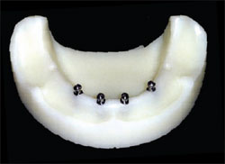
Using the hand driver or ratchet, complete the installation of the implant (Figure 4). Don’t be afraid to apply pressure. If you meet too much resistance, back the implant out and widen the osteotomy. The implant platform should be flush with the soft tissue ridge (Figure 5): The model illustrated here has no soft tissue, so the implants are shown sitting on the bone. Clinically, the collar abuts the soft tissue and the smooth surface of the shaft below the platform is in the soft tissue.
PROSTHETIC TECHNIQUE
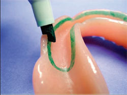
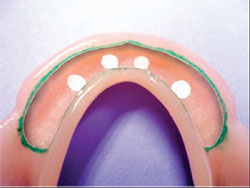
Using the marking pen, delineate the area of the denture to be relieved, about 2 mm from the edge of the flange and extended just short of the retromolar pads (Figure 6).
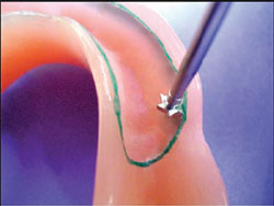
Using the half-round #1 denture cutting instrument, create a seam with an undercut at the 2 mm mark around the entire periphery (Figure 7).
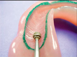
Using the #2 round diamond cutting instrument, groove out the remaining acrylic and smooth out the grooves with the #3 round carbide cutting instrument. This will result in a space about 1-1.5 mm deep within the borders of the delineated area (Figure 8).
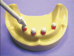
Place plastic marking caps on the four Atlas implants.
Cover the marking caps with Wite-Out™. (Figure 9).
Place the denture over the ridge in the correct approximate position and apply pressure against the marking caps.
Check the ridge side of the denture; there should be four recognizable marks indicating where the denture will have to be relieved to create clearance for the heads of the Atlas implants (Figure 10).
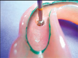
Using the #3 round carbide bur, hollow out the four marked areas to 4-mm depth (Figure 11). Remove the marking caps and try the denture on and off. It should not bind.
Use a toothbrush to remove excess acrylic and wet towel to remove the ink. Swab the patient’s ridge to remove any particles that might embed in the silicone reline.
Extrude Tuf-Link silicone material onto a pad and spatulate for 30 seconds.
Spread the mixed Tuf-Link along the seam and the relieved areas of the implants and fill the hollowed-out portion of the denture base (Figure 12). Do not be afraid to overfill because it is trimmed easily with a scissors.
Place the denture over the mandible from the posterior and have the patient bite down and hold the denture in place for 4-5 minutes.
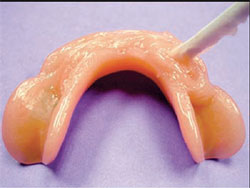
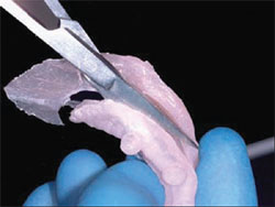
When the silicone reline material is set, carefully remove it from the denture and trim the excess with a scissors (Figure 13).
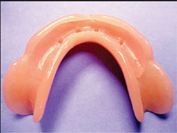
Press the trimmed silicone reline back into the denture base (Figure 14). Notice the four openings in the silicone reline that will grip the implant heads to provide retention and stabilization. The patient may sleep with the denture.
CONCLUSION
Narrow body implants are not meant to replace traditional wide body implants. But they offer a cost-efficient and realistic alternative for many patients who are never offered implant therapy because of thin ridges, lack of appropriate vertical or horizontal bone, and a multitude of other systemic, age, and cost factors.
For more information, contact:
Dentatus USA
Phone: 1-800-323-3136
Web: www.dentatus.com
References
1. Christensen G. 140th Chicago Midwinter Meeting 2005. Fixed, Implant and Removable Prosthodontics, Simple to Complex.This article was written by Keith Rossein, DDS, consultant, author, and lecturer. He is president of International Dental Consultants, a partner in www.webdentalmarketing.com, the editor and publisher of Implant News & Views, and is listed in the Seattle Study Clubs Speaker’s Bureau. He is a consultant for Dentatus.
DISCLAIMER
The preceding material was provided by the manufacturer. The statements and opinions contained therein are solely those of the manufacturer and not of the editors, publisher, or the Editorial Board of Inside Dentistry. The preceding is not a warranty, endorsement, or approval for the aforementioned products or services or their effectiveness, quality, or safety on the part of Inside Dentistry or AEGIS Communications. The publisher disclaims responsibility for any injury to persons or property resulting from any ideas or products referred to in the preceding material.
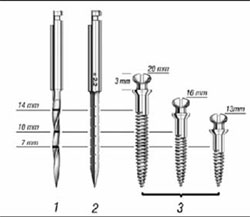 | 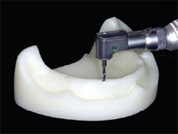 | |
| Figure 1 Options in the Atlas implants line. | Figure 2 Drilling flapless osteotomies. | |
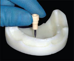 | 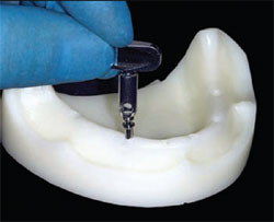 | |
| Figure 3 Implant insertion. | Figure 4 Completing the implant installation. | |
 |  | |
| Figure 5 Model showing the implant platform. | Figure 6 Delineation of the area of the denture to be relieved. | |
 |  | |
| Figure 7 Creation of a seam around the entire periphery with a half-round cutting instrument. | Figure 8 Grooving and smoothing the acrylic to create a space within the delineated borders. | |
 |  | |
| Figure 9 Marking caps are covered with Wite-Out. | Figure 10 Marks indicating where the denture will have to be relieved. | |
 |  | |
| Figure 11 Hollowing the marked areas with a round carbide bur. | Figure 12 Spreading Tuf-Link over the hollow in the denture base. | |
 |  | |
| Figure 13 Excess reline material is trimmed with scissors. | Figure 14 Trimmed silicone reline seated in the denture base. |

