

The Reality of Anatomy and the Triangle of Bone
Scott D. Ganz, DMD
“Reality of Anatomy” is a concept developed by the author to describe the anatomical relationship between the tooth, the surrounding alveolar housing, the clinical crown, the root, and other important anatomy.1 Most textbooks, manufacturers’ literature, journal articles, and meeting presentations describe a relationship of the tooth to bone as seen in Figure 1.2 These illustrations are acceptable in teaching the concept of crown-to-root ratio and are useful in describing certain procedures related to implant procedures. However, the cross-sectional anatomical representation does not reflect the true relationship of the tooth root and its surrounding bone. When placing implants, it is important that clinicians have a clear understanding of the anatomical complex.
The use of computed tomography (CT) scan technology as a tool for diagnosing and treatment planning dental implants has allowed a more accurate understanding of the tooth-to-bone anatomical relationship. Recent innovations and the proliferation of new cone beam (CBCT) machines, which are now small enough to fit in the dental office, have helped to focus implant industry on image-guided surgery and are gaining in popularity with clinicians worldwide.3 The CT images acquired from either conventional CT or newer CBCT machines produce 2- and 3-dimensional undistorted images from which accurate treatment plans can be developed and then translated into usable surgical templates.4-10
In Figure 1, (A) illustrates a healthy periodontal condition showing the ideal crown-to-root ratio, and (B) expresses the change in the surrounding bone, reflecting a diminished crown-to-root ratio. While these concepts are correct, and easily understood from these 2-dimensional illustrations, they do not reveal the true bone volume that surrounds the natural dentition. When trying to diagnose potential implant receptor sites, a lack of appreciation of the actual condition of the bone-to-tooth relationship can lead to significant problems.
If the placement of an implant into the residual socket site is envisioned, it may be expected that the facial-lingual dimension is sufficient to support both the implant and the restorative components. In reality, teeth are not surrounded by this volume of bone, and, in most cases, this representation is not accurate. Clinicians can finally gain a true understanding of actual bone anatomy with the use of CT scan technology and innovative diagnostic software. Clinicians have been able to visualize jaw anatomy in cross-sectional, axial, and panoramic views for more than 16 years, and recent innovations have allowed for true 3-dimensional reconstructions and stereolithographic models for improved presurgical prosthetic planning.11-17
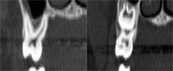
Figures 2A through 2E depict an actual CT scan of a 16-year-old patient, who was evaluated for endosseous implants to replace congenitally missing lateral incisors. A CT scan was necessary to assess the available bone anatomy for 2 implants in addition to helping determine the proximity and inclination of the adjacent root structures using 3-dimensional imaging. Figure 2A shows the cross-sectional image of a central incisor. This compelling slice exposes the clinician to actual fact in the understanding of the root-to-bone complex. The clinical crown is clearly visualized with the supporting root and pulp canal. The alveolar complex includes the surrounding bone, which extends to the floor of the nose, and the nasal cavity resides above the root structure. Close inspection exposes the fragile buccal/labial plate of bone and thin palatal. It is this view that makes one ask, “Where is the bone?” It must be remembered that this is a young adult without any bone loss or periodontal problems.
The dominant canine tooth (Figure 2B) follows a similar pattern as the incisor in terms of the amount of bone surrounding the tooth root. While many clinicians look to the height and width of available bone (which is certainly important), it is the author’s contention that the volume of bone is the most significant indicator in determining potential implant receptor sites. In this cross-sectional slice, the nasal cavity is evident as well as the anterior aspect of the maxillary sinus. Figure 2C shows a premolar tooth with similar findings of minimal existing bone thickness surrounding the roots. The pattern is repeated with both the molar and depictions of the developing dentition (Figure 2D and Figure 2E).
The initial cross-sectional view allows the clinician to examine vital anatomical structures in anticipation of planning for an implant-supported restoration. The ability to properly evaluate the diagnostic information provides clinicians with a simple decision tree of available treatment options. Cross-sectional slice number 49 depicts the severe resorption of the natural tooth root (Figure 3). The remaining bone housing or alveolus can be visualized as including borders of the nasal cavity and part of the hard palate. This view should be a cross-sectional slice at the midline of the tooth (mesial-distal) from the axial view (not shown). This gray-scale image is composed of the same information as presented by a periapical radiograph (ie, hard tissue is more opaque [whiter areas], soft tissue is less opaque [gray areas], and lack of any structure [air] is black). This is where the similarity to conventional dental radiology ends because the CT scan data can also determine bone density in terms of Hounsfield units.
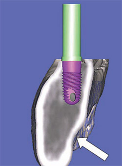
In Figure 4, the alveolus (outlined in light brown) contains both cortical and cancellous bone. The clinical crown is opaque and outline with the resorbed root. It is significant to note the amount of remaining bone that exists beyond the apex of the natural tooth. The area beyond the apex is often where the greatest volume of bone can be found. If the true relationship of the tooth-root-bone trajectory is not fully appreciated, problems can occur when placing implants. If the tooth was extracted, and an implant was placed following the extraction socket and root apex, the drill would perforate the facial cortical plate. This is especially true for the anterior maxilla. If not properly addressed and the clinician continued to place the implant, the apex would penetrate through the thin buccal plate leading to potential problems. However, the cross-sectional CT image does allow the clinician to understand the available bone, which often exists well beyond the apex of the tooth root. The potential for bicortical stabilization of the implant can be greatly improved with this enhanced ability to understand the existing anatomical condition.
TRIANGLE OF BONE
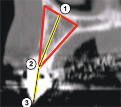
Once a cross-sectional image has been chosen, a unique concept has been developed by the author to appreciate the existing bone volume and aid in determining whether it is a positive receptor site. The Triangle of Bone (TOB)1 is a decision-making tree to determine the ideal placement for an implant within the parame-ters of the existing bone and the desired tooth position. Slice 49 shows a tooth that has a hopeless prognosis and will be extracted and replaced with an implant-supported prosthesis. The position of the implant can be completely arbitrary, or can be surrounded by the greatest volume of existing bone.
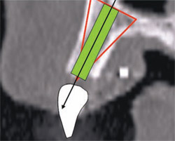
To apply the TOB concept to a cross-sectional slice, a specific triangular pattern can be placed over the image with the following specifications (Figure 5A):
- Start at the base of the bone on the facial or buccal aspect at the widest part of the bone housing, parallel to the floor of the sinus if visible.
- The second point connects the line at the widest portion of the palatal bone to create the base of the triangle.
- The apex of the triangle bisects the alveolar crestal bone, at the height of the crest, or a level where the top of the implant would be placed.
Once the triangle overlay has been determined the next step is to decide what kind of bone exists inside the TOB. The steps of the decision tree are:
- If there is sufficient volume of bone, the proper implant position can be determined, and successfully placed (includes height, width, and volume).
- If there is insufficient volume of bone, then either a grafting procedure or ridge splitting to gain width are suggested.
- No treatment.
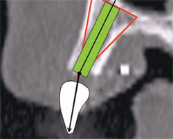
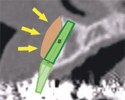
In this example, there was adequate height, width, and volume of bone to place an implant. The ideal placement within the most volume of bone should bisect the triangle, as shown by the yellow line connecting points 1 and 2 in Figure 5B(View Figure).
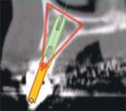
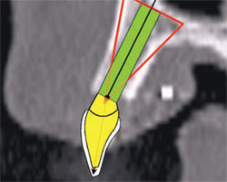
If there is a radiopaque template or an existing tooth present, the ideal position of the implant needs to be correlated to the tooth position.18-21 This is accomplished by connecting point 2 at the apex of the TOB to point 3 located at the incisal edge of the tooth (Figure 6B). The implant is initially placed to bisect the TOB (Figure 6C). This will allow for the greatest amount of bone surrounding the implant. The length and diameter of the implant can also be a factor in gaining bicortical stabilization for the implant. There is some latitude on the implant positioning (within the TOB), because it is the tooth position that guides and ultimately determines the angulation and emergence for ideal restoration.22 Placing a simulated abutment helps the clinician visualize the trajectory of the final restoration, and, with advanced software applications, it can be positioned to support the tooth in the most ideal manor. The abutment can then be extended into the tooth until it meets the incisal edge of the tooth. Depending on the restorative needs of the patient, whether cemented or screw-retained, the abutment can be straight or angulated. The position of both the implant and the abutment can then be tweaked to maximize the results. As this example indicates, the initial bisecting position was excellent for a cemented restoration.
Software Applications
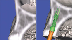
Currently available software applications, such as SimPlant® (Materialise, US Clinical Services, Inc, Glen Burnie, MD), feature the ability to view and interact with 2-dimensional cross-sectional slices and also reconstruct and slice through a 3-dimensional virtual model so that the relationship of the existing bone can be further evaluated. In Figures 6A and 6B, the implant is seen within the bony housing placed within the TOB. If there are any problems with the 3-dimensional positioning, they can be corrected interactively from either the full, axial, or cross-sectional 3-dimensional views. Therefore, this 3-dimensional view corroborates the positioning in the 2-dimensional cross-sectional view. It is the author’s opinion that interactive treatment planning using a virtual 3-dimensional model allows the clinician to assess the anatomy and position implants with greater accuracy than can be achieved with any 2-dimensional representations.1,11,12,14 The 3-dimensional reconstructed view of a virtual implant and abutment, with an overlay of the TOB, can be seen in Figure 6C.
Mandibular Implants
The mandible presents clinicians with a different set of parameters in terms of trajectories of tooth and bone and the proximity of the inferior alveolar nerve. The TOB concept can be applied to the mandible and can prove to be extremely useful in determining the appropriate course of treatment. One part of the decision tree is to pick the implant that will most likely succeed within the parameters of the available bone and the position and morphology of adjacent vital anatomy. This might mean using a narrower implant, which would be surrounded by more bone volume and potentially avoid perforating the lingual cortical plate and/or the inferior alveolar nerve.
Case Examples
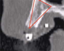
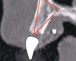
In the following examples, it is assumed that there is adequate space between the position of the inferior alveolar nerve and the implant. In Figure 7A, the tooth was hopeless and facial to its normal position and the implant was planned to be placed in an ideal position. Note the lingual concavity that cannot be detected with conventional panoramic or periapical radiography. Using 3-dimensional reconstruction, a wider, shorter, realistic, and simulated implant was placed in adequate bone to avoid potential problems near the lingual cortical plate or in proximity to the lingual concavity inferiorly (Figure 7B). The abutment projection appears longer than the implant. Therefore, when planning implants, it is important to pre-assess conventions such as crown-to-root ratio, which can be established before the finalization of the treatment plan. A longer, narrower, realistic implant placed within the mandible illustrates good positioning within the TOB. Slicing through the 3-dimensional virtual model empowers the clinician with significant advanced diagnostic capabilities showing how important the 3D models are in determining the final placement to avoid problems and maximize success. In Figures 7C and 7D, the mandible has been tilted slightly to show how the implant is embedded halfway into the bone. The implant was again placed within the parameters of the TOB.
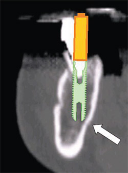
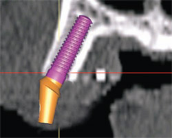
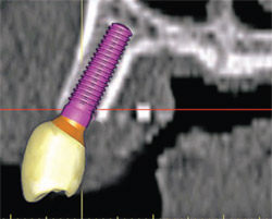
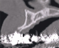
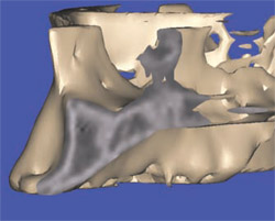
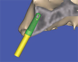
The latest software tools allow the clinician to take the information from the CT scan and successfully plan implant placement. In Figure 8A , there appears to be adequate bone to place an implant in the maxillary site. The TOB (seen in red) is created in the cross-sectional view to assess and then confirm the volume of bone (Figure 8B). The proposed position of the tooth should be visualized in the ideal restorative position on the CT scan. This can best be accomplished with a barium sulfate template that is worn during the scanning process to incorporate the fully contoured opaque tooth image (Figure 8C).18-21 In this example, there is adequate bone volume and bone density to plan for implant placement. The simulated implant is then positioned to bisect the triangle. In this example, the implant is parallel to the facial and palatal cortical plates of bone (Figure 8D).
In Figure 9A, a line can be drawn from the incisal edge of the tooth to the midline of the implant to help determine the type of abutment that will be needed to properly restore the case. The abutment shape can then be developed by the software application to provide support for the clinical crown. For this example, the custom-angulated abutment would be an acceptable 8 degrees off the centerline of the implant (Figure 9B).
Current software applications can now allow for a realistic simulated implant to be placed within the bone and soon the ability to place realistic abutments will equip the clinicians with even more exact tools to aid in the diagnosis and treatment-planning phase (Figure 10A). The next level of sophistication combines the implant, the abutment, and the virtual tooth to complete the process of total visualization of the end result (Figure 10B). Note that the implant is well placed within the TOB. Additionally, the ability to take the CT scan and treatment plan using interactive treatment planning software has allowed for CT-derived surgical templates to be fabricated to transfer the plan to the surgical site.4-10,15-17,23-25
The advantages of CT imaging allow clinicians to plan for ancillary procedures to help restore or manage the implant receptor site. In the example of a deficient ridge, the facial concavity can be clearly visualized, permitting a better understanding of the available options for both clinician and patient. The clinician can advise the patient that, in addition to the placement of an implant to support the missing tooth, treatment alternatives are available to replace the missing anatomy to gain an esthetic root emergence profile. This could be in terms of a bone or soft tissue graft procedure.
The advanced 3-dimensional tools inherent in CT imaging and interactive software applications empower the clinician to make the correct treatment planning decisions with confidence. The following 4 illustrations reveal a clinical presentation in the maxillary arch where there was not enough bone volume for the placement of an implant. Figure 11Acontains the cross-sectional image of a potential implant receptor site in the maxillary arch. The thin alveolar crest and facial concavity are apparent in this view, but would not be obvious in a periapical radiograph. The 3-dimensional reconstruction shows the true extent of the concavity, and the volumetric changes in the facial and lingual cortical bone (Figure 11B). If a realistic simulated implant were to be placed into this site, only a small portion of the implant would be embedded in the bone, leaving too many exposed threads, and lack of fixation (Figure 11C). The TOB concept helps the clinician understand that, in this case, there was not adequate bone for implant placement. Therefore, an alternate treatment plan could be developed, which would give the patient a chance to have an implant after adequate bone volume has been created with either particulate, block-grafting, or ridge-splitting techniques (Figure 11D).
CONCLUSION
The advent of CT-imaging technology provides clinicians with an advanced and improved set of tools to diagnose and treatment plan for dental implants. Although there is a large population of clinicians who still rely on conventional film, newer and more accurate modalities exist which surpass 2 dimensions and provide an unparalleled appreciation of underlying undistorted anatomy. CT imaging has been shown to be more effective than conventional panoramic or periapical radiographs for assessing anatomy,26 giving clinicians a true appreciation of the reality of anatomy. The ability to diagnosis and treatment plan dental implants in 3 dimensions with interactive planning software applications is clearly the future, and yet is readily available today. The link between the simulated plans to the surgical procedure is the CT-derived surgical template, which was not within the scope of this article. However, the data from these plans can be exported by various methods to create templates which transfer the accuracy of the scan to the surgical site.
The introduction of smaller CBCT machines has expanded access to this exciting technology during the past several years. The proliferation of these machines has helped the implant industry understand the clinician’s desire to remove all guesswork from the planning phase and the surgical aspect, thereby increasing accuracy and success. There are several machines currently available, including the i-CAT machine (Imaging Sciences International, Inc, Hatfield, PA), the NewTom 3G (APerio Services, LLC, Sarasota, FL), CB MercuRay™ (Hitachi Medical Systems America, Twinsburg, OH), the ILUMA (Imtec Corporation, Ardmore, OK) , and the 3D Accuitomo, (J Morita USA, Inc, Irvine, CA), with more machines scheduled to be released in the near future.
The purpose of this article was to alert clinicians of the 3-dimensional anatomical view presented by the current CT and CBCT technology. This quickly evolving technology is reacting to the demands of the marketplace. Original implant conventions are now being modified to include immediate or delayed loading protocols, increased esthetic demands, improved surgical techniques, advances in bone grafting and site development, and computer-milled titanium and ceramic abutments. CT imaging and diagnostics will play an essential part to ensure successful outcomes today and in the future.
DISCLOSURE
The author is a consultant for Materialise, US Clinical Services, Inc, Glen Burnie, MD.
References
1. Ganz SD. The triangle of bone—a formula for successful implant placement and restoration. Implant Soc. 1995;5(5):2-6.2. Shillingburg HT, Hobo S, Whitsell L. Fundamentals of Fixed Prosthodontics, 2nd ed. Hanover Park, Il: Quintessence; 1981:19.
3. Ganz SD. Use of conventional CT and cone beam for improved dental diagnostics and implant planning. AADMRT Newsletter, Spring Issue 2005. Available at: www.aadmrt.com/static.aspx?content=currents/ganz_spring_05. Accessed March 29, 2006
4. Klein M, Cranin AN, Sirakian A. A computerized tomographic (CT) scan appliance for optimal presurgical and preprosthetic planning of the implant patient. Prac Periodontics Aesthet Dent. 1993;5(6):33-39.
5. Van Steenberghe D, Malevez C, Van Cleynenbreugel J, et al. Accuracy of drilling guides for transfer from three-dimensional CT-based planning to placement of zygoma implants in human cadavers. Clin Oral Implants Res. 2003;14(1): 131-136.
6. Jacobs R, Adriansens A, Verstreken K, et al. Predictability of a three-dimensional planning system for oral implant surgery. Dentomaxillofac Radiol. 1999;28(2):105-111.
7. Fortin T, Champleboux G, Lormee J, et al. Precise dental implant placement in bone using surgical guides in conjunction with medical imaging techniques. J Oral Implantol. 2000;26(4): 300-303.
8. Besimo CE, Lambrecht JT, Guindy JS. Accuracy of implant treatment planning utilizing template-guided reformatted computed tomography. Dentomaxillofac Radiol. 2000;29(1):46-51.
9. Klein M, Abrams M. Computer-guided surgery utilizing a computer-milled surgical template. Pract Proced Aesthet Dent. 2001;13(2): 165-170.
10. Klein M. Implant surgery using customized surgical templates: the Compu-Guide Surgical Template System. Interview. Dent Implantol Update. 2002;13(6):41-46.
11. Rosenfeld AL, Mecall RA. Use of interactive computed tomography to predict the esthetic and functional demands of implant-supported prostheses. Compend Contin Educ Dent. 1996;17(12): 1125-1146.
12. Rosenfeld AL, Mecall RA. The use of prosthesis-generated computed tomographic information for diagnostic and surgical treatment planning. J Esthet Dent. 1998;10(3):132-148.
13. Amet EM, Ganz SD. Implant treatment planning using a patient acceptance prosthesis, radiographic record base, and surgical template. Part 1: Presurgical phase. Implant Dent. 1997;6(3): 193-197.
14. Ganz SD. CT scan technology—an evolving tool for predictable implant placement and restoration. Int Mag Oral Implantol. 2001;1:6-13.
15. Sarment DP, Sukovic P, Clinthorne N. Accuracy of implant placement with a stereolithographic surgical guide. Int J Oral Maxillofac Implants. 2003;18(4);571-577.
16. Ganz SD. Use of stereolithographic models as diagnostic and restorative aids for predictable immediate loading of implants. Pract Proced Aesthet Dent. 2003;15(10):763-771.
17. Sarment DP, Al-Shammari K, Kazor CE. Stereolithographic surgical templates for placement of dental implants in complex cases. Int J Periodontics Restorative Dent. 2003;23(3):287-295.
18. Israelson H, Plemons JM, Watkins P, et al. Barium-coated surgical stents and computer-assisted tomography in the preoperative assessment of dental implant patients. Int J Periodontics Restorative Dent. 1992;12(1): 52-61.
19. Basten CH. The use of radiopaque templates for predictable implant placement. Quintessence Int. 1995;26(9):609-612.
20. Borrow W, Smith JP. Stent marker materials for computerized tomograph-assisted implant planning. Int J Peridontics Restorative Dent. 1996;16: 61-67.
21. Basten CH, Kois JC. The use of barium sulfate for implant templates. J Prosthet Dent. 1996;76(4):451-454.
22. Ganz SD. What is the single most important aspect of implant dentistry? Implant Soc. 1994;5(1):2-4.
23. Sarment DP, Misch CE. Scannographic templates for novel pre-implant planning methods. Int Mag Oral Implantol. 2002;3:16-22.
24. Tardieu PB, Vrielinck L, Escolano E. Computer-assisted implant placement. A case report: treatment of the mandible. Int J Oral Maxillofac Implants. 2003;18(4):599-604.
25. Ganz SD. Presurgical planning with CT-derived fabrication of surgical guides. J Oral Maxillofac Surg 2005;63(9 Suppl 2):59-71.
26. Sonick M, Abrahams J, Faiella R. A comparison of the accuracy of periapical, panoramic, and computerized tomographic radiographs in locating the mandibular canal. Int J Oral Maxillofac Implants. 1994;9: 455-460.
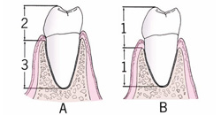 | ||
| Figure 1 The relationship of the tooth to bone. (A) A healthy periodontal condition showing the ideal crown-to-root ratio; (B) Note the change in the surrounding bone, reflecting a diminished crown-to-root ratio. | ||
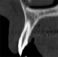 | 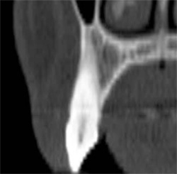 | |
| Figure 2A The cross-sectional image of a central incisor. | Figure 2B The dominant canine tooth follows a similar pattern as the incisor in terms of the amount of bone surrounding the tooth root. | |
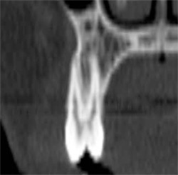 |  | |
| Figure 2C A premolar tooth with similar findings of minimal existing bone thickness surrounding the roots. | Figures 2D and 2E The pattern is repeated with both the molar and depictions of the developing dentition. | |
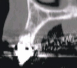 | 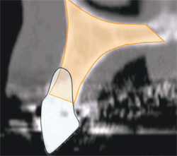 | |
| Figure 3 Cross-sectional slice number 49 depicts the severe resorption of the natural tooth root. | Figure 4 The alveolus (outlined in light brown) contains both cortical and cancellous bone. The clinical crown is opaque and outline with the resorbed root. Note the amount of remaining bone that exists beyond the apex of the natural tooth. | |
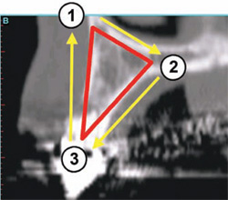 |  | |
| Figure 5A To apply the TOB concept to a cross-sectional slice, a specific triangular pattern can be placed over the image. | Figure 5B The ideal placement within the most volume of bone should bisect the triangle, as shown by the yellow line connecting points 1 and 2. | |
 |  | |
| Figure 5C The implant is initially placed to bisect the TOB. This will allow for the greatest amount of bone surrounding the implant. | Figures 6A and 6B The implant is seen within the bony housing placed within the TOB. | |
 |  | |
| Figure 6C The 3-dimensional reconstructed view of a virtual implant and abutment, with an overlay of the TOB, can be seen. | Figure 7A The tooth was hopeless and facial to its normal position and the implant was planned to be placed in an ideal position. Note the lingual concavity that cannot be detected with conventional panoramic or periapical radiography. | |
 | 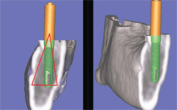 | |
| Figure 7B Using 3-dimensional reconstruction, a wider, shorter, realistic, and simulated implant was placed in adequate bone to avoid potential problems. | Figures 7C and 7D The mandible has been tilted slightly to show how the implant is embedded halfway into the bone, and the implant was again placed within the parameters of the TOB. | |
 |  | |
| Figure 8A There appears to be adequate bone to place an implant in the maxillary site. | Figure 8B The TOB (seen in red) is created in the cross-sectional view to assess and then confirm the volume of bone. | |
 |  | |
| Figure 8C A barium sulfate template is worn during the scanning process to incorporate the fully contoured opaque tooth image. | Figure 8D The implant is parallel to the facial and palatal. | |
 |  | |
| Figure 9A A line can be drawn from the incisal edge of the tooth to the midline of the implant to help determine the type of abutment that will be needed to properly restore the case. The abutment shape can then be developed by the software application to provide support for the clinical crown. | Figure 9B For this example, the custom-angulated abutment would be an acceptable 8 degrees off the centerline of the implant. | |
 |  | |
| Figure 10A The ability to place realistic abutments will offer even more exact tools to aid in the diagnosis and treatment-planning phase. | Figure 10B The next level of sophistication combines the implant, the abutment, and the virtual tooth to complete the process of total visualization of the end result. | |
 |  | |
| Figure 11A The cross-sectional image of a potential implant receptor site in the maxillary arch. Note that the thin alveolar crest and facial concavity are apparent in this view, but would not be obvious in a periapical radiograph. | Figure 11B The 3-dimensional reconstruction shows the true extent of the concavity, and the volumetric changes in the facial and lingual cortical bone. | |
 |  | |
| Figure 11C If a realistic simulated implant were to be placed into this site, only a small portion of the implant would be embedded in the bone, leaving too many exposed threads, and lack of fixation. | Figure 11D An alternate treatment plan could be developed, which would give the patient a chance to have an implant after adequate bone volume has been created with either particulate, block-grafting, or ridge-splitting techniques. | |
| About the Author | ||
 Scott D. Ganz, DMD Scott D. Ganz, DMD Clinical Assistant Professor Department of Restorative Dentistry University of Medicine and Dentistry of New Jersey Newark, New Jersey Private Practice Prosthodontics and Implant Dentistry Fort Lee, New Jersey | ||


