
Using Cone-Beam Computed Tomography and 3-Dimensional Implant Planning Software: The Laboratory Technician’s Role
Lars M. Hansson, CDT, FICOI
Abstract:
Once the restorative dentist has diagnosed the patient’s problem and starts to form a plan, the laboratory technician’s role is to present knowledge of materials and technical advice, confirming that the plan can be executed to completion. This article provides insight into the importance of collaborating with the laboratory technician early in the treatment planning, during restorative phases when restoring with dental implants, and when using a 3-dimensional interactive treatment planning software.
Using an Implant Planning Software to Communicate
There are several 3-dimensional (3D) interactive implant planning software programs on the market, all serving the same purpose: to aid in dental implant planning and placement (Figure 1). Using these treatment planning software programs is important to assure that placement of the dental implants does not compromise the long-term restoration or patient’s health, while giving the surgeon, restorative dentist, and technician a visual planning tool prior to the surgical and restorative involvement. These programs can also help determine the implant design and aid the surgeon and restorative dentist in selecting the appropriate abutment components. It is important that not only the surgeon and the restorative dentist understand how to use this software but also the technician should understand its capabilities.
The Laboratory Technician’s Role in Treatment Planning
These software tools will help in the 3D planning stage, but beforehand, the technician needs to perform the prediagnostic work, which involves photography, diagnostic wax-up, or diagnostic set-up (Figure 2 2A, 2B, 2C). When fabricating the diagnostic wax-up, the technician should understand that the ideal tooth width must correlate to the size of implant used for the radiographic prosthesis. For example, when placing a 4.3-mm implant, the width of the tooth needs to be 7.3 mm, allowing for 1.5 mm on each side of the implant for ideal interproximal bone to maintain the papilla. The mistake often made by laboratories and dentists is the use of denture teeth when creating a surgical or radiographic guide for the surgeon: this will result in a crowding of the implants because denture teeth are not designed for diagnostics of implant placement. Before creating the guide or diagnostic wax-up, the technician should understand the masticatory system and the importance of stabilizing the existing occlusion while following the Dawson concept and working from centric relation.1 After the diagnostic work has been carefully evaluated and finished, the radiographic scanning appliance can be fabricated.
Once the patient has been scanned and the images uploaded to a 3D treatment planning software, there are many ways of sharing this information with the laboratory technician. One powerful, efficient option is an internet conference meeting, such as GoToMeeting (Figure 3). This process can include all the team members in live, hands-on interdisciplinary treatment planning. Coordinating an online meeting is an effective, yet simple way to allow the restorative team to communicate and share ideas without having to be in the same room. By employing this live input from the team members, issues such as angulation, number of implants, and options for restorative materials can be discussed. Looking at the 3D treatment plan, a knowledgeable technician can evaluate if the restoration can be a screw-retained or cement-retained restoration. At this point, any modifications can be made on the 3D software plan before finalizing the treatment and having a surgical template fabricated. Pricing of the restorative options can be discussed once all members of the team agree on a treatment plan and restorative option.
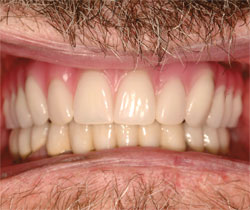
Selecting the implant system when planning the restorative component is important because both the surgeon and restorative dentist need to be aware of the prosthetic options supplied by these implant systems. Many of the restorative options that dental laboratories use today employ CAD/CAM (computer-aided design/computer-aided manufacturing) technology for better esthetics and longer-lasting restorations (Figure 4A and Figure 4B).
Restorative dentists need to have close relationships with their dental laboratories and know which digital CAD/CAM systems they are using or the options for outsourcing. This information should indicate to the restorative dentist which implant system the surgeon should use. CAD/CAM technology is being used not only for fixed restorations but also for patients who need removable prosthetics. CAD/CAM overdenture bars need spacing for attachments and the acrylic overdenture. Using 3D software to measure the available space on the scan helps when selecting the appropriate attachment (Figure 5A and Figure 5B). At this time, there are a limited number of outsource centers for CAD/CAM milled overdenture bars and often technicians have to rely on the outdated wax and cast technology. This will change in the near future as more CAD/CAM systems are developed and more implant platforms become available.
Conclusion
With careful preoperative planning and treatment coordination using a 3D treatment planning software, the dental healthcare team can achieve a predictable final result. For the laboratory technician, this software has become one of the most effective tools to communicate and assure that the placement of the implant is prosthetically driven by the restorative team.
References
1. Dawson PE. Functional Occlusion: From TMJ to Smile Design. 3rd ed. St Louis, MO: Mosby Elsevier; 2006.
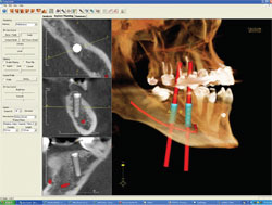 | FIGURE 1 EasyGuide™ image showing the planning of two posterior implants with the long axis in red following the curve of Spee (photograph courtesy of Keystone Dental). | ||
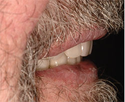 2A | 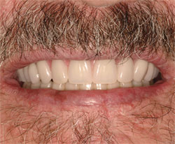 2B | ||
 2C | FIGURE 2A THROUGH FIGURE 2C Diagnostic set-up to evaluate the occlusion, phonetics, and esthetics prior to radiographic scanning appliance fabrication. Photographing each step gives the technician a better visual for the fabrication of the final or interim restoration. | ||
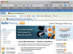 | |||
| FIGURE 3 Example of an internet option for web meeting. | |||
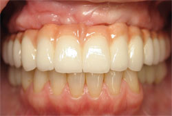 | 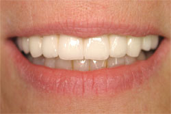 | ||
| FIGURE 4A AND FIGURE 4B Example of restoration planned with 3D planning software: screw-retained all zirconium bridge (Procera™,Nobel Biocare,Yorba Linda, CA). | |||
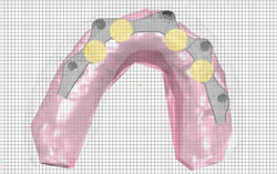 | 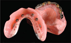 | ||
| FIGURE 5A AND FIGURE 5B CAD/CAM bar design (BIOMET 3i, Palm Beach Gardens, FL) showing the choice of attachment and design of bar, to give the patient the best retention and stability. | |||
| |||

