

Grafting With Cortical Bone Pins (The Alabama Graft)
Wilkie J. Stadeker, DDS
This article will discuss a graft technique first brought to the author’s attention a few years ago by the Department of Periodontics at the University of Alabama School of Dentistry. While this technique may not be suitable for all situations, it can be very useful for socket preservations and ridge augmentations. This technique has several advantages over other grafting techniques, including no membranes to remove, no screws to retrieve, and no collapsing of the graft. Because of its origin, the author calls this grafting technique the “Alabama Graft.”
Materials
The Alabama Graft has three components. The first is Regenaform paste (Exactech, Inc, Gainesville, FL). This material is a mixture of demineralized bone matrix; demineralized, freeze-dried bone allograft (60% by weight); mineral-retained cortical and cancellous chips (20% cortical/80% cancellous); and a natural biological gelatin carrier.1 These components make Regenaform osteoinductive and osteoconductive.2 Osteogenesis is the transfer of vital cells to the area being grafted. Osteoinduction is the conversion of cells into bone via the osteoblastic pathway. Osteoconduction provides the necessary building blocks to form bone and sufficient space for these building blocks to grow. These three factors are important when choosing a grafting material because they determine how effective the material will be.3
To ensure that each lot of Regenaform has osseoinductive and osteoconductive properties, a sample from each lot made is placed into an intramuscular rat model and tested for its ability to induce bone formation. This procedure is the gold standard established by Urist4 and is an important concept to understand when choosing a grafting material. Regenaform has a 5.5- to 6-month breakdown time, as indicated by literature supplied by the manufacturer.
Regenaform is one of the essential parts of the Alabama Graft because it can be easily molded into different shapes, accommodating such procedures as the grafting of a socket or ridge augmentation. This molding characteristic results from the natural biological carrier in Regenaform, which, when mixed with sterile water or blood, forms a clay-like consistency.
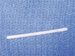
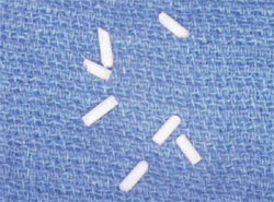
The second component of the Alabama Graft is cortical bone pins. The cortical bone pins are manufactured by the Muscular Skeletal Transplant Foundation and they come in several pre-measured lengths. The pins measuring 40 mm in length and 2 mm in width are recommended. The cortical pins are produced from struts taken from femoral, tibial, and humeral shafts. Each end of the cortical pin is chamfered.
The pins serve several purposes. One such purpose is tenting to prevent socket preservations and ridge augmentations from collapsing, particularly in a site that has lost facial or lingual bone. Although titanium mesh and metal pins are one alternative solution to this problem,5,6 mesh exposure can result because of the bulk of the titanium and metal material. Having to remove the titanium mesh and metal pins after the graft has healed is another drawback of using those materials, and the metal pins can leave large voids after removal, thereby potentially affecting the graft.
In addition to the tenting function, the cortical pins provide the space necessary for osteoconduction to occur. Another purpose of the cortical pins is stability. By having the cortical bone pins stick out in different directions, the Regenaform can solidify around them and give the graft added retention. The cortical pins also increase the amount of cortical bone available by traversing the graft from outside to inside. This is an important benefit, because the amount of cortical bone available will greatly increase the success rate of the implant.
Several studies have found that the amount of cortical bone has a significant positive influence on the implant. A study by Lin et al7 found that larger implant strain values were found in cortical bone, indicating that implants were better able to handle strain in a cortical bone environment. They also found that bone strain increased with decreasing bone density and was affected primarily by bone quality. Even in cancellous bone, they found that strain on the implants increased as quality of bone decreased.
During implant placement, the pins can become totally encased in the graft, with anecdotal data suggesting denser hard tissue formation at the pin sites. Although no histological evidence exists, the healed grafted bone seems to be Zarb type 1 or type 2 bone, in the author’s clinical opinion.8 He has found that even when he starts out with Zarb type 3 or 4 bone, he is able to convert it to Zarb type 1 or 2 by doing an Alabama Graft.
An abstract presented at the 2005 annual meeting of the Academy of Osseointegration9 discussed the type of bone present after several ridge augmentations. The abstract discussed the effectiveness of resorbable membranes used in lateral ridge augmentations. In the study, 25 patients with ridges less than 5 mm had a lateral ridge augmentation. The authors used Regenaform and the Gore Resolut Adapt LT Membrane (W.L. Gore & Associates, Inc, Flagstaff, AZ) (the same membrane used in the Alabama Graft). After 6 months of healing, a biopsy was taken from all sites using a 2-mm trephine. The biopsies were submitted for histomorphic analysis. Descriptive analysis showed evidence of remodeling and new bone surrounding the implanted bone fragments. Additionally, within these samples, marrow tissues containing adipocytes were evident and areas of complete remodeling of the bone fragments with new bone were found with viable osteocytes present within the bony matrix. If bone formation was obtained using only Regenaform and a membrane, then using cortical bone pins, in the author’s opinion, may certainly help the process even more.
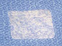
The final component of the Alabama Graft is a long-term restorable membrane. While any number of membranes can be used, the Gortex Resolut Adapt LT is suggested because of its long breakdown time (according to the manufacturer, the membrane remains substantially intact for 16 to 24 weeks), flexibility, thinness, softness, and suppleness. This membrane is also very easy to trim. The membrane is composed of 50% polyglycolic acid (PGA) and 50% trimethylene carbonate (TMC).10 The membrane also has an open structure, similar to mesh. The structure allows tissue integration, thus holding the membrane in place. Like all Gortex products, the membrane is well studied. Several studies have found that it performs well in all types of guided tissue regeneration procedures.11-13
Grafting Procedure
When performing an Alabama Graft, one of the most important considerations is site closure. This is important because exposure of the graft material or membrane may result in failure. When selecting a site, one should take a clinical assessment of whether there is adequate attached tissue. If there is not sufficient tissue, a connective tissue or free gingival graft should be considered. One should also become familiar with the subepithelial-releasing incision. A few of these incisions on the underside of the flap can go a long way in helping site closure.
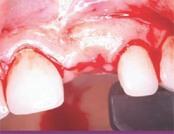
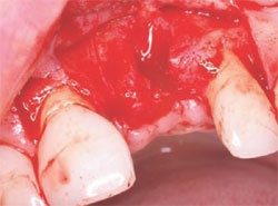
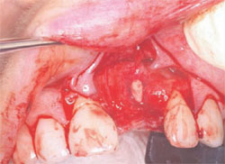
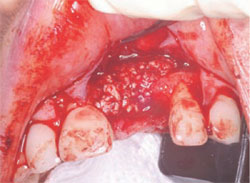
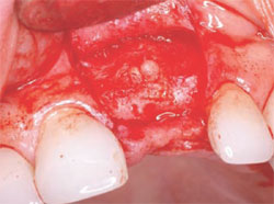
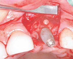
The following case was selected for an Alabama Graft. The patient was a 54-year- old woman whose central incisor root canal had failed. A full-thickness flap was reflected with vertical-releasing incisions, one tooth to the right and one tooth to the left of the site to be grafted (Figure 1). Upon reflection of the flap, a tremendous amount of bone damage was noted (Figure 2). The damage was mostly to the facial aspect of the ridge, making this ridge a Seibert Class I defect.14,15 The site was cleaned, decorticated, and a cortical bone pin was placed mid-defect (Figure 3).
Preparation of the cortical bone pins was done in two steps (Figure 4 and Figure 5). In the first step, the 40-mm segment was cut into 4-mm sections. This 4-mm section length was found to have worked best in previous grafts, although any desired section length can be used, depending on how the graft presents. In the second step, the site where the pin was to be placed was prepared in a precise fashion using two implant osteotome burs. The site was first drilled with a 1.5-mm bur to a 2-mm depth. The site was then widened with a 2-mm bur, down to between 0.5 mm and 1 mm in depth. By preparing the site in this manner, a tapered effect was achieved. The tapering creates retention of the cortical pin when it is inserted, as the pin has a 2-mm diameter. Once the fit of the cortical pin was verified and there was no movement when slight pressure was applied, the flap was then prepared.
In preparing the flap, care was taken to make sure there was closure over the pin and sufficient space to allow for graft placement. The Resolut Adapt LT membrane was then trimmed to fit the desired location (Figure 6). The texture and handling of the Resolut Adapt LT membrane made suturing and positioning easy. The membrane was trimmed so that at least 2 mm of membrane was covering the edge of the defect to be grafted. The grafting material was then prepared by mixing the Regenaform with room-temperature saline. The grafting material also can be mixed with the patient’s blood, if desired. The Regenaform comes with a marked measuring syringe to ensure that the dentist uses the correct amount of blood or saline solution in the mixture.
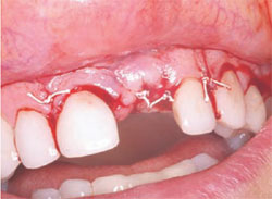
After mixing the Regenaform, the grafting material and membrane were put in place (Figure 7). When placing the grafting material, one should always make sure not to overfill the defect or create extra bulk that might affect closure or the wearing of a temporary prosthesis. The site was then closed using the provided Gortex sutures (Figure 8). The advantage of these sutures is that they are very strong, making primary closure easy. They also decrease the amount of wicking into the graft because they are made from a synthetic material.
The graft was allowed to heal for 6 months, a period of time that is well established in periodontal literature and that should be followed.16 Although some patients may advocate for a shorter period of healing before the implant is placed, the clinician should make clear that any deviation from the recommended period of healing may have negative consequences for the graft.
After the necessary healing period had passed, the site was reflected, giving keen consideration to esthetics. A full-thickness flap with a vertical-releasing incision was created to get the best possible esthetics. The papillae were left in place to improve the emergence profile. Once the flap was reflected, the graft was inspected for voids or defects. The graft was found to be solid with no defects (Figure 9). This result is one of the best advantages the Alabama Graft has over metal pins. If metal pins had been used in this case, they would have had to be removed and voids would have resulted. Here, the cortical bone pin remained but, as shown, it was totally encased in hard tissue. The newly grafted bone is often very resistant to drilling. This may result because the Regenaform has cortical bone chips and the bone pin is composed of solid cortical bone that may supersaturate the graft with cortical bone.
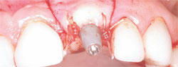
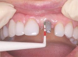
The next step was to choose the type of implant to be placed. A one-piece implant in the anterior location was preferred because the author finds it often provides better esthetic results than a two-piece implant. A Nobel Biocare (Yorba Linda, CA) NobelDirect® implant was placed, taking great care to place the implant in the best esthetic position, as outlined in a previous article on esthetic loading of implants by this author.17 After the esthetically loaded implant was placed (Figure 10 and Figure 11), it was sutured with vicral sutures and an esthetic temporary crown was placed on it (Figure 12). The author always places esthetically loaded implants in light occlusion. The temporary crown plays a very critical role at this point. It allows the patient to evaluate shape, position, and color, and, based on the author’s clinical experience, may also allow for better postoperative healing and less papilla death. After 6 months of healing, the temporary crown was removed and excellent healing was evident. The implant had no mobility, no pockets, and no bleeding upon probing (Figure 13).
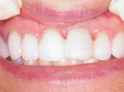
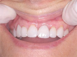
The implant can be prepared at this point, if necessary. After very little preparation, an impression was taken and the temporary crown was relined and replaced. After laboratory fabrication, the final crown was cemented with excellent results. The patient was very happy with the final result and stated that it met all of her expectations (Figure 14).
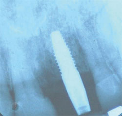
An x-ray was taken 2 years after placement of the crown and no bone loss was noted (Figure 15). In almost every of the approximately 20 Alabama Grafts the author has performed, no bone loss was observed. The reason for this is unclear and warrants additional research. The author surmises that it may be that the Alabama Graft somehow inhibits bone loss by being supersaturated with cortical bone. Branemark18 stated that one should expect 1.5 mm of bone loss in the first year and 0.1 mm every year after placement, but he did not provide a reason for this projected bone loss.
Conclusion
This case demonstrated the Alabama Graft being used in a ridge augmentation. The ridge augmentation depicted had a cortical facial bone defect, although the technique may be used successfully in other types of ridge defects as well, including knife-edge defects. The author has also used this technique successfully in socket preservations.
The Alabama Graft technique has several advantages over other grafting techniques. One advantage over block grafting techniques is avoiding the need to harvest the graft.19-21 In addition to this, even if one uses a non-harvested block grafting technique, one may have to sacrifice so much of the host bone that if the technique does not work, the dentist is left with a much worse situation. Block grafts are also more difficult to manipulate around a corner. The Alabama Graft technique also has advantages over titanium mesh membrane and metal pins, including not having to remove the pins or mesh membrane in a second-stage surgery.
The Alabama Graft technique also produces very dense bone, resulting in minimal or no bone loss when implants are placed into this bone. Finally, the Alabama Graft technique provides a significant amount of versatility. One can perform this technique in almost any situation and place the pins and the bone in almost any position. The technique will likely evolve over time so that different sized cortical bone pins and cortical bone chips are available for different grafting situations.
References
1. Levine R, Horowitz R. Bone reconstructive surgery for implant site preparation. Functional Esthetics and Restorative Dentistry. 2007;1(2):2-11.
2. McAllister BS, Haghighat K. Bone augmentation techniques. J Periodontol. 2007; 78(3):77-396.
3. Hollinger JO, Brekke J, Gruskin E, Lee D. Role of bone substitutes. Clin Orthop Relat Res. 1996;324: 55-65.
4. Urist MR, Jurist JM Jr, Dubuc FL, Strates BS. Quantitation of new bone formation in intramuscular implants of bone matrix in rabbits. Clin Orthop Relat Res. 1970;68: 279-293.
5. Assenta B, Piattelli M, Scarano A, et al. Localized ridge augmentation using titanium micromesh. J Oral Implantol. 2001; 27:287-292.
6. Hempton TJ, Fugazzotto PA. Ridge augmentation utilizing guided tissue regeneration, titanium screws, freeze-dried bone, and tricalcium phosphate. Implant Dent. 1994; 3: 35-37.
7. Lin C, Wang J, Ramp L, Liu P. Biomechanical response of implant systems placed in the maxillary posterior region under various conditions of angulation, bone density and loading. Int J Oral Maxillo Fac. 2008;23(1): 57-64.
8. Zarb GA, Symington JM. Osseointegrated dental implants: preliminary report on a replication study. J Prosthet Dent. 1983;50(2):271-276.
9. Geurs N, Reddy M. The efficacy of resorbable membranes for use in lateral ridge augmentations. Abstract 20th Academy of Osseointegration. March 10-12, 2005.
10. del Castillo R. Defect morphology: effects on regenerative predictability and membrane selection. Compend Contin Educ Dent. 2000;21:383-5, 388, 390; 396.
11. Sandberg E, Dahlin C, Linde A. Bone regeneration by the osteopromotion technique using bioabsorbable membranes: an experimental study in rats. J Oral Maxillofac Surg. 1993;51(10): 1106-1114.
12. Lorenzoni M, Pert C, Polansky R, et al. Evaluation of implants placed with barrier membranes. Clin Oral Impl Res. 2001:13: 274-280.
13. Celletti R, Davarpanah M, Etienne D, et al. Guided tissue regeneration around dental implants in immediate extraction sockets: comparison of e-PTFE and a new titanium membrane. Int J Periodontics Restorative Dent. 1994;14(3): 242-253.
14. Seibert JS. Reconstruction of deformed, partially edentulous ridges, using full thickness onlay grafts. Part I: technique and wound healing. Compend Contin Educ Dent. 1983;4(5):437-453.
15. Seibert JS. Reconstruction of deformed, partially edentulous ridges, using full-thickness onlay grafts. Part II: prosthetic/ periodontal interrelationships. Compend Contin Educ Dent. 1983;4(6):549-562.
16. Nevins M, Jovanovic SA. Localized bone reconstruction as an adjunct to dental implant placement. Curr Opin Periodontol. 1997;4:109-118.
17. Stadeker W. Aesthetic loading of implants. Dent Today. 2008;27(3): 104, 106-109.
18. Adell R, Lekholm U, Rockler B, Brånemark P. A 15-year study of osseointegrated implants in the treatment of the edentulous jaw. Int J Oral Surg. 1981;10(6):387-416.
19. Hwang K, Shim K, Yang S, Park C. Partial-thickness cortical bone graft from the mandibular ramus: a non-invasive harvesting technique. J Periodontol. 2008;79(5): 941-944.
20. Pikos M. Block autografts for localized ridge augmentation: Part I: the posterior maxilla. Implant Dent. 1999;8:279-285.
21. Pikos M. Block autografts for localized ridge augmentation: Part II: the posterior maxilla. Implant Dent. 2000;9:67-75.
 |
 |
|
| Figure 1 Incision design. | Figure 2 Full-thickness flap. | |
 |
 |
|
| Figure 3 Placement of cortical pin. | Figure 4 Cortical bone pin. | |
 |
 |
|
| Figure 5 Sectioning of cortical bone pin. | Figure 6 Gortex Resolute Adapt LT Membrane. | |
 |
 |
|
| Figure 7 Placement of Regenaform. | Figure 8 Surgical closure. | |
 |
 |
|
| Figure 9 Healing at 6 months. | Figure 10 Placement of the implant. | |
 |
 |
|
| Figure 11 Closure of the implant site. | Figure 12 Implant temporary. | |
 |
 |
|
| Figure 13 Probing of the implant. | Figure 14 The final restoration, courtesy of Dr. Ron Hull. | |
 |
||
| Figure 15 X-ray 2 years postoperative. | ||
| About the Author | ||
 Wilkie J. Stadeker, DDS Wilkie J. Stadeker, DDSPrivate Practice Atlanta, Georgia |
||

