

A Predictable Procedure for Managing the Resorbed Posterior Maxilla With Short, Sintered Porous-Surfaced Dental Implants
Douglas Deporter, DDS, PhD
Recent advances in technique have led to the simplification of the restoration of the resorbed posterior maxilla with dental implant-supported prostheses. While direct open window sinus elevations to access the sinus cavity continue to be used1 (particularly when multiple implant sites in a single sextant require sinus augmentation), many patients with minimal subantral bone height can be more easily and less expensively managed with the indirect sinus elevation approach. As originally described by Summers2 and confirmed by others,3-5 an indirect, minimally invasive, low-risk sinus elevation procedure can be performed using hand-held, end-cutting osteotomes and a surgical mallet to elevate the sinus floor in an area localized to the apex of the implant osteotomy.
The height of subantral bone existing at the intended implant site is first determined using a panoramic, tomographic, or, ideally, a computed tomography radiographic image. Knowing this height and assuming that the bone is primarily types III or IV,6 a series of osteotome tips of gradually increasing diameter driven by tapping with a surgical mallet is used to develop the osteotomy to a depth short by ~1 mm of the sinus floor. If the bone quality is denser (eg, type II),6 a pilot bur may be needed to create the initial site depth (again staying ~1 mm short of the sinus floor) thereby avoiding excessive force with the osteotomes that couldproduce vertigo as an untoward effect.7 The bone through which the osteotome advances becomes compacted and acts as a “ceiling” for the osteotomy socket. This autogenous plug of bone will remain attached to the Scheiderian membrane of the sinus cavity and act as a buffer to protect this membrane from damage when the sinus floor is ultimately breached. Nevertheless, Summers2 has advocated that an exogenous particulate graft material be added to augment this autogenous plug before proceeding to advance the largest diameter osteotome tip through the remaining ~1mm of subantral bone, thereby up-fracturing the sinus floor.
The limitation in using this technique with most threaded implants is that when the existing subantral bone height is ≤4 mm, failure rates are appreciably higher than when the original bone heights are ≥6 mm. Depending on the design of the threaded implant used (eg, machined, acid-treated, particle-blasted, or titanium plasma-sprayed), failure rates in bone heights of ≤4 mm may range from 14% to 27%.4,8 These less than favorable outcomes likely relate to the need to use these implants in lengths of at least 13 mm in the maxilla to ensure long-term implant success under loading.2 It is known that the more the sinus membrane needs to be elevated, the greater the risk of sinus membrane damage9 and potential loss of the graft material into the sinus cavity proper.
More favorable results in ≤4 mm of subantral bone have been reported when the indirect sinus elevation approach is combined with short sintered porous-surfaced dental implants.5 In a series of 70 patients with 104 Endopore® (Innova Life Sciences Corporation, Toronto, Ontario, Canada) sintered porous-surfaced implants (primarily 7mm in length) the failure rate was reported at 1.9% after a mean functional time of >3 years10 (2 of the 104 implants failed under unusual patient circumstances unrelated to the initial subantral bone height). Sintered porous-surfaced implants achieve integration by bone ingrowth into the porous outer surface zone11 rather than by linear bone-to-implant contact as generally occurs with threaded implant designs.12 The resulting 3-dimensional mechanical interlocking between this truly porous (pore size range 50 µm to 200 µm) implant surface zone and the bone tissue that has developed within it during the initial integration process (Figure 1) allows for optimal stress transfer at the bone-to-implant interface13,14 and no need to use implants longer than 7 mm.15,16
A slightly modified osteotome sinus elevation procedure has been described for use with sintered implants.5 Criteria for successful case selection are listed in Table 1. Patients should be nonsmokers without a history of chronic sinus infection. The selected sites should have an initial subantral bone height of ≥3mm and adequate alveolar ridge width to preserve a minimum of 1.8 mm of original bone both buccally and palatally after implant placement to minimize crestal bone loss in the immediate postoperative period.17 Patients should be placed on amoxicillin (or an appropriate alternative antibiotic) starting 24 hrs before surgery (and continued for a total of 5 days [author’s preference]) and a strictly sterile surgical technique should be used throughout. Only 7-mm-long (with a diameter of 4.1 mm or 5 mm depending on implant location and alveolar ridge width available) Endopore implants should be used so that the greatest sinus membrane elevation will not significantly exceed 4 mm (eg, in a site with initial subantral bone height of 3mm) with little risk of membrane damage.9 The healing interval required for initial implant integration (generally between 3 and 6 months) will depend upon the amount and type of graft material used [the author has routinely used Bio-Oss® cancellous bone particles (Osteohealth Corporation, Shirley, NY)] and the resultant time required for this material to become consolidated with new bone. Once integrated, the implants may be restored as either implant-to-implant splinted fixed bridges or single crowns,15,16 the latter being preferred to ensure full loading of the bone-to-implant interface (Figures 2; 3; 4).
SURGICAL STEPS
The surgical steps5 are listed in Table 2. With the aid of a surgical implant placement guide, the intended implant sites are marked with a small (#4 or #6) round bur before proceeding to the osteotomes provided by the manufacturer (Innova LifeSciences). There are three tapered osteotomes available for use with the Endopore implant. The smallest diameter (1.6-mm cutting tip diameter) osteotome tip and a surgical mallet are next used to initiate site development, remembering to stop short of the sinus floor by ~1 mm. At this point, a periapical radiograph can be taken with the osteotome tip in situ to verify the depth of instrument penetration. The second (2.2-mm diameter at the cutting tip) and third (largest diameter, 2.8-mm diameter) osteotome tips are then used to the same depth. The osteotomy “ceiling” should be viewed frequently to ensure that the plug of autogenous bone compacted by the osteotome tips is clearly visible. At this point, a mineralized particulate xenograft or alloplastic material suitable for sinus grafting is added to the partially developed osteotomy. With this added buffer layer, the largest diameter osteotome tip and mallet are used to up-fracture the sinus floor. A sudden change in resistance to the advancing osteotome tip will indicate that the sinus floor has been breached. Thereafter, more graft is added and the osteotome advanced an additional 1 mm into the sinus domain, and this sequence of adding graft and advancing 1 mm at a time repeated until the full depth of 7 mm is achieved. The final instrument used is the Endopore-specific trial-fit gauge.5 This instrument has the shape and dimensions of the implant being used (7-mm-long x either 4.1-mm or 5-mm diameter at its widest and coronal dimension), and is connected to an osteotome handle and tapped to its fully seated position (ie, to a depth of 7 mm). If a 7-mm-long x 5-mm-diameter implant is planned, both the 7-mm x 4.1-mm and the 7-mm x 5-mm trial-fit gauges should be used in sequence to expand more gently and avoid fracturing the cortical plates of bone. When the entire conical gauge tip is submerged in bone, the operator is assured that the corresponding implant also will be fully submerged. Next, the implant is inserted (taking care not to contaminate the sintered implant surface) and fully seated with the mallet and an implant-seating driver tip. As a final step, a hand-held hex driver tip should be used to ensure that the healing cap is tight and the implant immobile.
DISCUSSION
To date, the technique has been used by the author as described in sites with ≥3 mm of original bone height, although some further modifications are being tested regarding whether or not an exogenous graft is really needed, and whether sites with <3 mm of subantral bone can be managed with predictable success. At this time in the author’s experience, the described technique should be followed in sites with 3 mm to 5 mm of subantral bone. However, since some authors have suggested that the Scheiderian membrane can be elevated without adding exogenous graft particles in either a direct open window18 or indirect osteotome approach,19 in sites with >5 mm of subantral bone height the author now generally does not add graft particles but rather only the compacted and apically displaced autogenous bone plug is used for the sinus floor elevation (Figure 5).
Additional support for this approach is provided by a recent animal investigation20 in which small sintered porous-surfaced implants were placed into rabbit maxillary sinuses using osteotomes. On the test side, Bio-Oss particles were used as a graft while on the control side of each animal no graft was used before placing the implant. Histomorphometric assessment of bone-to-implant contact of test vs control implants indicated similar levels of bone ingrowth, suggesting that the sintered surface layer was adequately osteoconductive by itself when the periosteal layer of the Schneiderian membrane was perturbed by localized sinus floor elevation using osteotomes.
In sites with <3 mm of original subantral bone height, the author has used a small rotary trephine to free up a circular plug of bone similar to the approach used by Summers21 in his “future site development” osteotome procedure and by Fugazzotto22 in his single-step implant placement technique with textured threaded implants in sites with ≥4 mm of subantral bone. Therefore, in sites with <3 mm of bone, once the trephined plug is movable, it is gently displaced into the sinus domain with an osteotome tip to the depth of 7 mm either with or without the addition of exogenous graft particles and the Endopore implant inserted using a submerged technique (Figure 6). Because of the larger degree of sinus membrane elevation required and the minimal original bone available to integrate with the implant, longer initial submerged healing intervals (ie, ≥8 months) are used with this modified method. It should be noted, however, that there are no prospective study data available as yet to support this application of the approach in <3 mm of subantral bone with simultaneous placement of a sintered porous-surfaced implant.
CONCLUSION
Ongoing data collection for the implant placement technique described in this article confirms that the combination of short, sintered porous-surfaced dental implants and the indirect, osteotome-mediated, localized sinus elevation procedure is a highly predictable, minimally invasive mode to address the restoration of the resorbed posterior maxilla with implant-supported fixed partial prostheses. The procedure can be performed with predictable success in sites with ≥3 mm of original subantral bone and appropriate alveolar ridge width.
Acknowledgments
The author wishes to thank Nancy Valiquette and Lynda Woodstock for administrative assistance in preparing this manuscript.
Disclosure
The author receives grant/research support from Innova LifeSciences.
References
1. Garg AK. Augmentation grafting of the maxillary sinus for placement of dental implants: anatomy, physiology and procedures. Implant Dent. 1999;8(1): 36-46.
2. Summers RB. The osteotome technique: part 3-less invasive methods of elevating the sinus floor. Compend Contin Educ Dent. 1994;15(6):698-708.
3. Coatoam GW, Krieger JT. A four-year study examining the results of indirect sinus augmentation procedures. J Oral Implantol. 1997;23(3): 117-127.
4. Rosen PS, Summers R, Mellado JR, et al. The bone-added osteotome sinus floor elevation technique: multicenter retrospective report of consecutively treated patients.Int J Oral Maxillofac Implants. 1999;14(6): 853-858.
5. Deporter DA, Todescan R, Caudry S. Simplifying management of the posterior maxilla using short, porous-surfaced dental implants and simultaneous indirect sinus elevation. Int J Periodontics Restorative Dent. 2000;20(5): 476-485.
6. Lekholm U, Zarb GA. Patient selection and preparation. In: Branemark P-I, Zarb G, Albrektsson T, eds; Tissue-Integrated Prostheses. Osseointegration in Clinical Dentistry. Chicago, Ill: Quintessence; 1985:199-209.
7. Simmons JJ, Triplett, RG, Schow S. Benign paroxysmal positional vertigo as a complication associated with osteotome use in the maxillofacial region. Int J Oral Maxillofac Implants. 2005;20:477. Abstract.
8. Toffler M. Osteotome-mediated sinus floor elevation: a clinical report. Int J Oral Maxillofac Implants. 2004;19(2):266-273.
9. Reiser GM, Rabinovitz Z, Bruno J, et al. Evaluation of maxillary sinus response following elevation with the crestal osteotome technique in human cadavers. Int J Oral Maxillofac Implants. 2001;16(6):833-840.
10. Deporter DA, Caudry S, Kermalli J, et al. Further data on the predictability of the indirect sinus elevation procedure used with short, sintered, porous-surfaced dental implants. Int J Periodontics Restorative Dent. 2005;25(6): 585-593.
11. Pilliar RM. Overview of surface variability of metallic endosseous dental implants: textured and porous surface-structured designs. Implant Dent. 1998;7(4): 305-314.
12. Hagi D, Deporter DA, Pilliar RM, et al. A targeted review of study outcomes with short (<_7 mm) endosseous dental implants placed in partially edentulous patients.J Periodontol. 2004;75(6):798-804.
13. Oyonarte R, Pilliar RM, Deporter DA, et al. Peri-implant bone response to orthodontic loading: part 2. Implant surface geometry and its effect on regional bone remodeling. Am J Orthod Dentofacial Orthop. 2005;128(2): 182-189.
14. Pilliar RM, Shagalijs G, Meguid S, Deporter DA. Threaded versus porous-surfaced implants as anchorage units for orthodontic treatment: 3-D finite element analysis of peri-implant bone tissue stresses. Int J Oral Maxillofac Implants. 2006. In press.
15. Deporter DA, Todescan R, Riley N. Porous-surfaced dental implants in the partially edentulous maxilla: assessment for subclinical mobility. Int J Periodontics Restorative Dent. 2002;22(2):184-192.
16. Rokni S, Todescan R, Watson P, et al. An assessment of crown-to-root ratios with short sintered porous-surfaced implants supporting prostheses in partially edentulous patients. Int J Oral Maxillofac Implants. 2005;20(1): 69-76.
17. Spray J. Black CJ, Morris HF, et al. The influence of bone thickness on facial marginal bone response: stage I placement through stage II uncovering. Ann Periodontol. 2000;5(1):119-128.
18. Lundgren S, Andersson S, Gualini F, et al. Bone reformation with sinus membrane elevation: a new surgical technique for maxillary sinus floor augmentation. Clin Implant Dent Relat Res. 2004;6(3):165-173.
19. Winter AA, Pollack AS, Odrich RB. Placement of implants in the severely atrophic posterior maxilla using localized management of the sinus floor: a preliminary study. Int J Oral Maxillofac Implants. 2002;17(5): 687-695.
20. Rahmani M, Shimada E, Rokni S, et al. Osteotome sinus elevation and simultaneous placement of porous-surfaced dental implants: a morphometric study in rabbits. Clin Oral Implants Res. 2005;16(6):692-699.
21. Summers RB. The osteotome technique: part 4-future site development. Compend Contin Educ Dent. 1995;16(11): 1080-1099.
22. Fugazzotto P. Immediate implant placement following a modified trephine/osteotome approach: success rates of 116 implants to 4 years in function. Int J Oral Maxillofac Implants. 2002;17(1):113-120.
 Figure 1 A backscatter scanning electron microscopic image of the proximal surface of a sintered porous-surfaced implant that had been in function in a dog mandible for 14 months. The crestal bone stabilized slightly coronal to the machined collar-to-sintered surface junction (arrow). |
 |
|
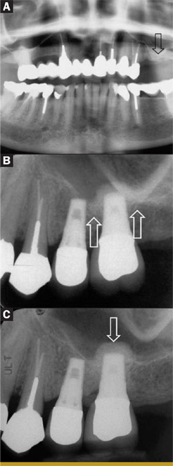
| Figure 2 A preoperative panoramic radiograph showing ~3 mm subantral bone height in the location of the former upper left first molar (arrow). B Baseline radiograph at 1 month after the insertion of the nonsplinted crowns on the implants replacing the maxillary left second bicuspid and first molar teeth. The original sinus floor can be seen partially discerned (arrows). C Follow-up radiograph after 3 years in clinical function. The grafted Bio-Oss® site (arrow) at the implant apex can be seen to be denser (ie, more infiltrated with new bone) than in the baseline image (B). (Prosthetic restoration by Dr. Richard Cameron.) | ||
 |
 |
|
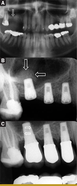
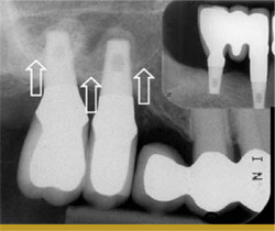
| Figure 3 A Preoperative panoramic radiograph showing 2 mm to 4 mm of subantral bone height in the location of the former maxillary right first molar (arrow). B A periapical radiograph taken immediately after implant placement. Graft particles can be seen localized to the apex of the implant replacing the first molar (arrows). No graft was used for the other two implants. C A periapical radiograph taken after 1 year in function with three individual nonsplinted crowns. New bone has formed on both the mesial and distal aspects (arrows) of the segment of implant root placed into the sinus domain. (Prosthetic restoration by Dr. Richard Cameron.) | Figure 4 A periapical radiograph of two maxillary molar sites restored with 7-mm-long Endopore® implants at sites with slightly < 3 mm of original subantral bone after 2 years in function with single, nonsplinted crowns. The original sinus floor is marked with arrows while the grafted areas are seen localized to the implant apices. The smaller radiographic image in the upper right corner shows that the opposing arch was restored with two 7-mm Endopore® implants and a three-unit fixed implantsupported bridge. (Prosthetic work performed by Dr. Reynaldo Todescan.) | |
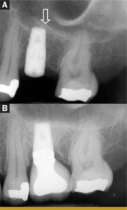 Figure 5 (A) An immediate postoperative periapical radiograph of an implant placed in a site that had approximately 6 mm of original subantral bone height. A small segment of sinus floor has been up-fractured as a "trapdoor" opening towards the distal (arrow). (B) The same implant after 2 years in function with a single implant crown. Bone has formed at the implant apex with the formation of a new sinus floor. (Prosthetic restoration by Dr. Reynaldo Todescan.) 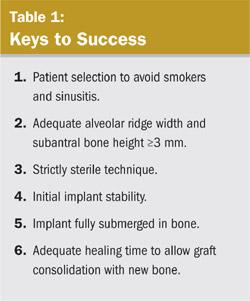 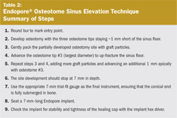 |
 |
|
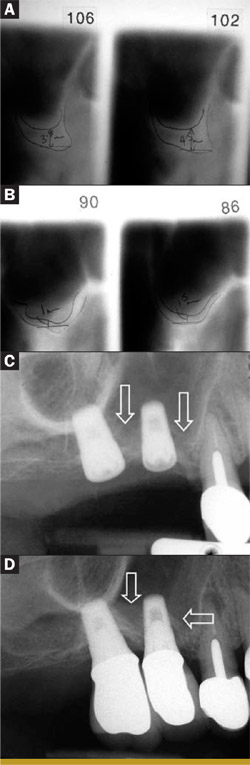
| Figure 6 (A) Preoperative tomographic tracing of the site of the former maxillary right first molar tooth. The ridge dimensions are estimated at 3.5 mm to 4.5 mm subantral bone height and an adequate width for a 5-mm-diameter implant. (B) Preoperative tomographic tracing of the site of the former maxillary right second bicuspid. The ridge width is good but the subantral bone height is estimated at 1 mm to 1.5 mm. (C) An immediate postoperative radiograph of the implants placed in the sites shown in (A) and (B). A 3-mm trephine was used to free up the 1-mm to 1.5-mm plug of bone in the bicuspid site before adding graft particles and a 7-mm 4.1-mm Endopore® implant. The straightforward osteotome technique was used with the molar site followed by placement of a 7-mm 5-mm Endopore®. The Scheiderian membrane between the two implants and mesial to the bicuspid implant can be seen to have been elevated by the added graft particles, which in this case are barely radiopaque (arrows). (D) A periapical radiograph taken after the two individual nonsplinted crowns have been in function for 1 year. New bone has formed around a major portion of both implant roots (arrows). The contiguous first premolar tooth has a failing endodontic treatment and will be extracted and replaced with a third implant. (Prosthetic restoration by Dr. Richard Cameron.) | ||
| About the Author | ||
 Douglas Deporter, DDS, PhD Douglas Deporter, DDS, PhDProfessor Discipline of Periodontology & Oral Reconstruction Center Faculty of Dentistry University of Toronto Toronto, Ontario, Canada |
||

